
TDR (Time Domain Reflectometry) is a measurement system that is especially adapted to the problems of telecommunications engineering. It is used to analyze and locate faults in electrical lines, line terminations and connections, electronic components and networks over a broad frequency range or to measure cable length. TDR reflectometers are also used for soil moisture measurement deriving the moisture content from the value of the relative permittivity εr. For small band applications the FDR system (Frequency Domain Reflectometry) is usually preferred. Here the test signal is a sinus voltage of variable frequency. A suitable measurement device determines the standing wave ratio or magnitude and phase of the reflection coefficient as a function of the input signal. Resonance frequencies can be determined very quickly and accurately using this method. For digital signals of high bit rates, e. g. in communication engineering, the broadband matching of electrical components and lines is important. This means in the whole frequency range from DC to eventually several gigahertz no reflections may appear. TDR measurement provides an easy and fast method for broadband analysis since the fast pulses used for measurement simulate exactly actual operation.
Measurement System
An impulse with a rise time as short as possible is launched into the device under test, e.g. a line of unknown impedance or with imperfect termination. The pulse width can be of arbitrary length, but it should be longer than the time window under consideration to avoid that reflections and the falling edge of the pulse reach the launching point at the same time. For the time window under consideration the pulse thus equals a step function. An oscillograph for the analysis of the test signals is inserted between the output of the pulse generator and the device under test. If the line is not perfectly terminated it takes twice the envelope delay time until the reflected signal reaches again the launching point and its shape and amplitude can be analyzed. In reference to the input signal a reflection coefficient can be determined that contains all information about magnitude and phase of the reflected signal. Figure 1 shows, where the test signal is measured and how the device under test is connected.
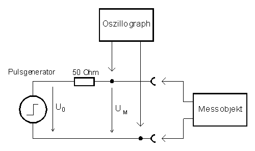
Figure 1: Equivalent Network for TDR Measurements
There are several possibilities to connect an oscillograph:
- High-Impedance Laboratory Oscillograph
Generally possible, but usually a high-impedance oscillograph cannot be used due to its small bandwidth. - Oscillograph with a 50 Ω input
An analog or digital oscillograph with a 50 Ω input can be connected to the line under test over a matched T-junction. The analysis of the test signal is more difficult because the T-junction weakens the signal by a factor of 2 (6 dB). - Sampling Oscillograph
A Sampling Oscillograph with a feed-through input allows to connect the test signal through without any losses. - Special Coupler
A special couper, that does not influence the reflected wave, allows to connect any 50 Ω oscillograph.
The impulse generator and the oscillograph have to be matched well to the system impedance of 50 Ω, since otherwise multiple reflections may occur. Figure 2 shows the measurement setup using the TDR 3000. The impulse generator and a special coupler are integrated into the TDR 3000.
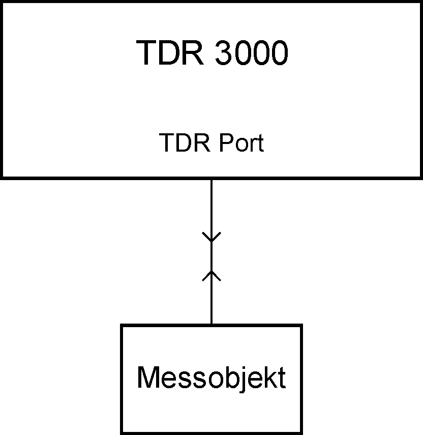
Figure 2: TDR Measurement Setup using the TDR 3000
Figure 3 shows several examples for line terminations including the voltage UM to illustrate the measuring system. We always consider only the rising edge of the test impulse. The left part of the diagrams is always the same and represents the outgoing wave. After the time T the reflected wave is added. T is twice the propagation time of the line under test including the short line inside the special coupler.
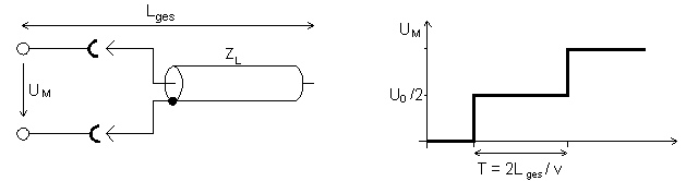 a) Open-ended Line 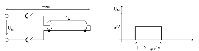 b) Shorted Line 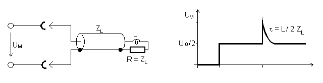 c) Inductive Termination 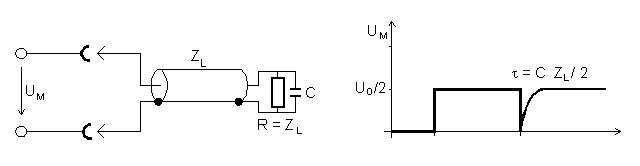 d) Capacitive Termination 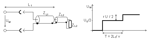 e) Mismatched Termination or Transition |
| Figure 3: Examples for TDR Measurements |
- a) Open-ended Line
- An open-ended line (reflection coefficient r = +1) produces a reflected wave of the same amplitude as the outgoing wave. Thus after the time T double the signal amplitude is measured at the input.
- b) Shorted Line
- The short circuit at the end of the line (reflection factor r = -1) produces a reflected wave with the amplitude -U0/2, that results in voltage of zero at the input after the time T.
- c) Inductive Termination
- A perfect impedance matching with R=ZL would not produce any reflection. But the inductance connected in series to R acts from our idealized point of view as a big resistor to the rising edge of the test pulse. Therefore the reflection coefficient r is equal to +1 at the beginning and after an exponential transition the matched state with r=0 is reached.
- d) Capacitive Termination
- A capacitor parallel to the resistor R=ZL acts like a short circuit with r=-1.
- e) Mismatched Termination or Line Connection
- A termination with R > ZL produces a reflection with a reflection coefficient 0 < r < +1. A transition to a line with a line impedance ZL2 > ZL1 has the same effect. The reflected wave has an amplitude of r * U0/2.
These examples that imply a perfect step function and idealized components can only be reproduced approximatively in practice. The finite rise time of the test impulse limits the system bandwidth and only allows a resolution in the range from 1 to 10 millimeter cable length. For demonstration purposes one should therefore always choose big reactances and line lengths. The examples were chosen because they are easy to verify in practical experiments and thus get to know the TDR measurement system. Some of the result can be achieved also using other methods, but in most cases the descriptiveness of the TDR system is a big advantage. Just think about a strip line with different line impedances or a longer bus line with several driver ports whose reflection characteristics would hardly be measurable using other methods.
Downloads
 Introduction to TDR Measurements